|
Add an AM Filter to the Drake TR-4 by Giorgio - IN3IEX |
|
Introduction
This modification enables the addition of an INRAD 8-pole 6.4 kHz AM filter to the Drake TR-4 transceiver. Details For installing the 9 MHz filter for AM, the new idea is to switch the filter with relays driven by a PowerMOS and an optocoupler that intercepts the small constant current (through the 3.3 Mohm resistor) that unbalances the diode balanced modulator while transmitting AM (the current is present also while receiving). In the Figure 1 you see the Inrad AM filter and the two relays that are used to intercept the two wires that go to the SSB crystal filter that is near the VFO connector (non X filter). 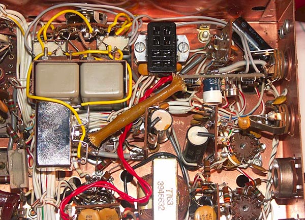 Figure 1 - Added Switching Circuitry AM and non-X SSB filters are therefore interchanged by the relays. The unused filter is connected to ground. One relay for input switching and grounding, the other for output switching and grounding. The schematic the switching circuitry is shown in Figure 2. The 3.3 MOhm resistor that must be intercepted is on the board with the red wires near the 6AQ5 socket. See Figure 3.  Figure 3 - Tap into 3.3 Meg Ohm Resistor The additional custom board with optocoupler, PS rectifier and MOS is near the VFO socket. In the brown insulating tube there is a 10 ohm resistor in series with 12 VAC, it powers the board. The MOS has a 6.2 Mohm resistor between gate and source to convert the small current from the optocoupler to gate voltage. The LED of the optocoupler is connected to +150V, then its cathode is connected to the 3.3 Mohm resistor that biases the balanced modulator and (also) to ground via a 4.7 Mohm resistor (or a combination of resistor and trimmer) which gives more bias to the LED. As before this arrangement is connected to the balanced modulator only in AM mode by the mode switch. No modification to the front panel is required, the mod is 100% reversible. For better shielding I later used shielded cables for connecting the AM filter to the relays and I also connected the coils of the two relays to the nearest ground with 10nf capacitors (not shown in Figure 1). Operation To operate in standard AM mode with SSB selectivity filter, please follow the instructions as reported in the TR4 manual. To enable the 6.4 kHz AM filter for receiving, the SIDEBAND switch must be rotated from the X position to the other position. Transmit frequency will not change and the transmitter will emit the AM rated power. AM filter can only be used by selecting the AM mode with the mode switch. Transceiver tuning to the correspondent station is best performed with the SSB filter (SIDEBAND X position), then it is suggested to switch to the AM filter for optimum reception. Best regards. IN3IEX - Giorgio Fontana, Trento, Italy (JN56NB). Here is a PDF version, suitable for printing. |