|
An AM Modulator for Modern Transceivers by Bob - K1VUB |
|
This
is not a “nuts and bolts” construction essay. I
have written this to stimulate the minds of hams that wish to have
Amplitude Modulation with some real punch from their “rice
box” type transceivers. I have this circuit in my Ten-Tec
Paragon 585, which has only AM receive capability, as
delivered from
the factory.1 The Paragon 585 uses 9 MHz for the
IF, and therefore I designed this circuit for same. The ALC is also a
problem with many transceivers, and I shall address this issue, as
well.
This modulator can supply 150 – 200% positive modulation while giving only 100% negative modulation, thus, not causing you to splatter all over the band with the heavy modulation. Don’t get me wrong. I am not telling you it’s ok to use the whole 200% positive. You need to remember that some receivers have straight diode detectors, and the 200% positive swing will likely overload them. This distortion will get you some bad reports very quickly. 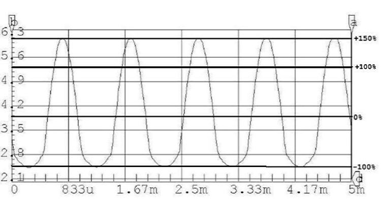 Figure 1 Figure 1 shows the waveform taken at the output of the first op-amp of the modulator shown below, with a 1 kHz signal applied to the input. The negative swing is being compressed and can be seen as 100%, while the positive swing is well over 100%. Additionally, the output does not go through the AM filter, so you may need to restrict the audio frequency range at the input if this your case as well. The DC coupling passes the lows down into the region below the ability of most receivers. Receivers with oscilloscopes connected to the IF. may see the lows that are transmitted by this modulator, but most receiver audio amplifiers are not up to the job. I tried a similar circuit to this one with a CA3028 single balanced modulator, but I had difficulty with carrier level stability vs. temperature. I’m sure that it could have been corrected, but I get impatient easily. I therefore selected the Motorola (On Semiconductor) MC14962 for the modulator (U3) as I had used them before in other projects where they worked well, and I had them in the junk box. All the other parts are standard except the toroid transformer in the output of the balanced modulator. This transformer is trifilar wound on a small core. It needs to be capable of resonating with C1 paralleled with C5 at the frequency you need to drive the transmitter, 9 MHz in my case. 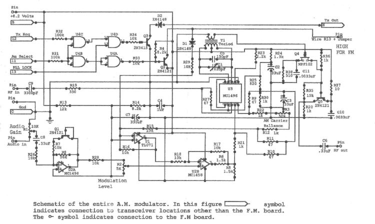 Figure 2 - Modulator Schematic (click here for printable version) Figure 2 is the full schematic of the AM modulator. The first op-amp, U2a, provides amplification of the audio. The amplitude of the positive swing is that of R26 to R8. The negative swing limiting is the result of R26 to R7 and Q1. The actual value of R7 is dependent on the diode “on” value of Q1. The values shown on the schematic deliver over 200% positive swing related to the negative. The final ratio is set by potentiometers R1 and R2. U1 provides the correct(ed) voltage for the inverting input of U2b. As it can be seen, any change in the setting of R2 will change the static balance of the balanced modulator U3. It will be necessary to alternately adjust all 3 potentiometers to get the proper carrier and modulation levels. The amplification of the RF output from the balanced modulator is provided by Q4 and Q5. Here again, the devices were those at hand. This stage must provide sufficient RF voltage for the AM and FM requirements. Since the AM modulator must pass the FM signal, it is necessary to provide gain enough to recover the losses of the balanced modulator in order to achieve full AM modulation peaks in the AM mode, and full output when the transceiver is in the FM mode. My transceiver supplies only about 8.2 Vdc regulated to the AM modulator board, which makes the rail-to-rail operation of the op-amps a bit tight and makes 200% positive modulation unachievable. There are higher voltages available, but a regulated source is needed. I have plans to add a regulator circuit to the transceiver that will supple 10 volts to solve that problem, and give me more gain margin in the RF output circuits as well. The circuit has been operated on the bench with 10 volts, and goes over the 200% mark easily. 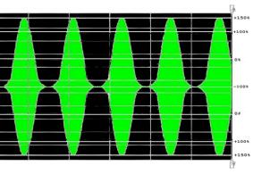 Figure 3 shows the output of Q5. Notice the compression is a replication of Figure 1. I must warn the reader that there is no “hard” limiting, and a good strong “yeahllow” into the microphone will result in over modulation. As a matter of fact, the modulator will cross over and go into double sideband. Let a word to the wise be sufficient. The logic device(s) U4 Q2 and Q3 are to control the keying of the transmitter, and the selection of the FM or AM modulator. I am not including the details of their operation, as it is very basic and may not apply to other than the Ten-Tec Paragon 585 transceivers. This brings us to the modifications of the Paragon 585 FM board, under which I installed my AM modulator board. In the Paragon 585, the FM board is mounted on standoffs in the top front. This allows one to install the new modulator under the FM board with standoffs between them, and some very short connections between the two. 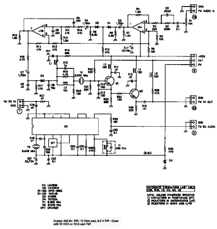 Figure 4A - Paragon FM Board Figure 4a shows the circuit of the factory FM board. The board will need the removal of one capacitor, a jumper, and the lifting of one end of a resistor. 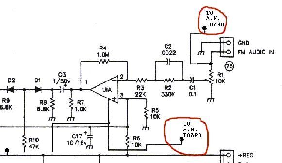 Figure 4b - Audio Modifications to FM Board Figure 4b shows part of the FM board audio section modifications. The amplifier designated as U1A, has the Vcc supply removed by the lifting of one end of a jumper. One end of the resistor R10 has one end lifted as well. These two lifted ends are connected together and to pin 5 on the AM modulator board. Pin 4 of the AM modulator board is connected to the FM board audio input connector, and Vcc for the AM modulator board pin 1 is supplied by the “REG” voltage on FM board. 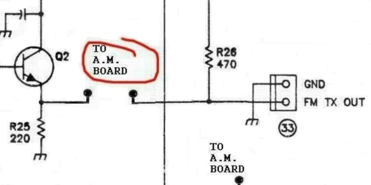 Figure 4c - RF Modifications to FM Board Figure 4c shows part of the FM board RF section modifications. The RF pins are connected in place of C16. This concludes the changes to the FM board. 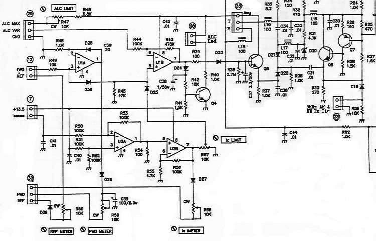 Figure 5 - Paragon ALC Circuitry Now for the “partie irresistible”. The ALC gets a boot! Figure 5a shows the original ALC circuit. Notice the AM/FM modulated RF insertion to the far right. The trick is to allow the ALC circuit have a limiting influence on the two pin type diodes D21 and D22, but not be the device by which the transmitter output level is controlled. This will allow the carrier level to be set independently from the maximum peak power output. 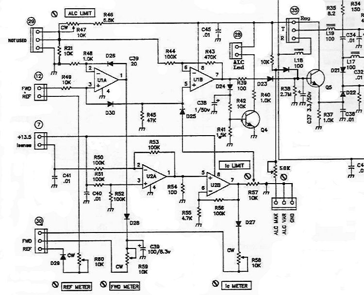 Figure 5b - ALC Modifications Figure 5b shows the changes made to the ALC circuit. The only new parts needed are a diode (1N4148), two resistors, one potentiometer, and one connector. Connector #29 is no longer used to connect the ALC front panel control. This control is now connected to the unnumbered connector labeled “ALC MAX, ALC VAR, and GND. The “ALC LIMIT” adjustment potentiometer is adjusted for full rated power output from the transceiver in the “TUNE”3 mode (or maybe a bit more if you have the courage). No other adjustments are made from the original settings. The front panel ALC knob now should be called “Power Output” not ALC4, and in turn, sets the RF gain of the transmitter. I set this adjustment for full power in the “TUNE” mode. The 50k undesignated potentiometer connected to unnumbered connector will set the RF gain range of the ALC front panel “Power Output” control. When the unit is operated in the AM mode, the carrier level must be reduced to allow for the maximum positive peaks. When my transceiver is operating on AM, the carrier is at about 25 watts carrier, and the ALC led flickers on some voice peaks. This is really simple, and may be applicable to transceivers other than the Paragon. The PIN diode circuit here is probably a bit different than what is used by other manufacturers, but the principal could very well apply. The object is to get the ALC out of the business of transmitter Output Level Control, and let it be an Output Limiter. There were several changes made to the digital control circuits in the Paragon 585 to allow access to the mode selection and keying functions. These changes are pertinent only to a Paragon 585, so I feel that they are beyond the scope of this writing. Now get on AM and keep the mode alive and well. 73’s K1VUB Notes: 1 Later versions of the Paragon such as the 586, have AM modulation, but the method was not acceptable to this author 2 The MC1496 or MC1596 may be out of production however there should be other devices that will perform as well. 3 The tune mode places the transceiver in full output transmit in its original unmodified condition. 4 The Paragon 585 actually called this control “RF PWR”. This however, as can be seen, was in error. The control only adjusted the maximum ALC limit, |