| Another
Ranger Restoration by Ken - K6FC |
|
Several
years ago at the Hosstraders Hamfest I picked up a Johnson
Ranger. I had wanted one to restore and although this one was
no beauty contest winner, it came home with me.
Move ahead to winter 2008-2009 and it was time to get started as cold weather had set in and outside activities were limited. I gathered up as much information as I could find on the Internet and started the task. Kudos to WA1HLR, AD5X, W3AM, and K4XL for their fine articles on Ranger modifications. Their write-ups covered a major part of the effort. A download of the Ranger manual from BAMA completed the necessary documentation. Like most tasks of this sort, one makes changes: some due to parts availability and some the result of a “better mousetrap” determination. My goal was to get the Ranger operational again and if possible add to the body of work already available. My first task was to open up the Johnson and get an idea of what lay ahead. After removing the cabinet it was obvious there was going to be a lot of cleaning involved. To say it was filthy was an understatement and the original soldering job (was it a kit?) was not exactly mil-spec! Plastic insulated solid wire was used – a lot of that had to go! In addition the Johnson PTT modification had been made and that process had butchered the wiring around the mode switch. This was not going to be as easy as I had hoped! I removed the front panel knobs and then the front panel. All the knobs came off with only a little effort (better than a rust bucket Viking II I restored several years ago). With the panel off it was obvious a decent cleaning job was going to require some disassembly and that began with the mode switch which had attracted a lot of “grunge” and chunks of solder. I thought to myself this was going to complicate things later in the rewiring process – but it had to be done. After removal and thorough cleaning (I used “Bar Keepers Friend” and a toothbrush) it looked almost new. But how did all those contacts and wipers work together? The following table is the result of a visual and ohmmeter study of the two switch wafers:
At this point some serious rewiring was going to be required and I had to decide what principal features I wanted to incorporate. This was my list:
These requirements were not quite compatible with the mode switch connections and try as I might I couldn’t do everything I wanted: specifically to have HV on the modulator only in the phone position and to get 6146 grid drive in the tune position. Looking at the switch it was apparent there was enough length available to add a wafer. Checking the junk box I found a two-pole five-position ceramic wafer that would work as long as I used some shorter spacers between the wafers. This addition can be seen in Photos 2 and 3 and serves the two functions noted above. Actual wiring of the new SW4 is described later in the text. Other Modifications Planned From the Start
Later Issues:
Power Supplies All rectifier tubes were replaced by silicon. The HV filter capacitor, C77, was replaced by two 470 uF 450 volt caps in series (with 470K equalization resistors) for a total of 235 uF. The LV filter capacitor, C78, was replaced by a single 470 uF 450 volt unit. The bias filter capacitor, C90, was replaced with a 100 uF 150 volt cap. The modulator bias source is identical to that shown in the W3AM article. Neutralization A typical ARRL Handbook circuit was used here. L12 was replaced by a 2.5 mH RF choke and C36 (.005 uF) was replaced by two silver micas (620 pF above the chassis and 330 pF below). A glass piston trimmer from the 6146 plate to the bottom of L6A through an insulated feed-thru completes the circuit. Photos 4 and 5 show the details of this addition. Wiring A lot of the original wiring was simply removed as the plastic insulation in many cases had melt spots due to excessive application of the soldering iron or dropped solder. In the high voltage circuits 1000 volt insulated wire was used. The original AC power cord was tossed and a modern three wire grounded polarized cord installed. Other The tables below outline the wiring connections to the modified mode switch.
The schematic diagram (thanks to TinyCad) shows the modifications made to the 6146 PA and 6AQ5 clamp tube circuits as well as the connections to the two transmit relays. The 1N4007 diode allows the multiplier tube, V4, to be active in the tune mode (this allows PA grid current tuning) while isolating other circuits that require low B+ only during transmit. With the move of resistor SH4 to the cathode of the 6146, the meter switch wiring will change and that is noted in the schematic diagram. While this change was made primarily to protect the meter, getting the high B+ off the meter switch seemed like a reasonable measure. Mechanical/Physical The Ranger came with only one of the three long screws that secure the cabinet to the transmitter chassis. Substitutes were made using 10-24 “all-thread” with nuts silver soldered at one end of the all-thread to tighten things up (note: flat washers should be used between the nut and chassis). The knobs and front panel were carefully cleaned with mild soap to remove dirt and tobacco smoke residue and then lightly buffed after a light application of furniture polish. The cabinet paint was heavily scratched. The paint was removed by glass bead blasting and then primed and repainted gray. Not a close match to the front panel color, but it doesn’t look bad! Photos |
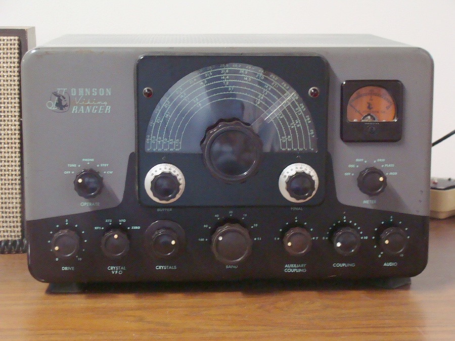
Photo 1 - Front Panel
Note the
mode switch with three wafers.
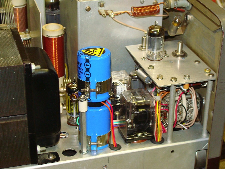
The
socket for the 6AX5 is now used for a 2PDT relay. The 4PDT
miniature relay is located just behind this relay where the old Johnson
PTT relay was located.
The
socket space for the 5R4 accommodates the two 470 uF 450 volt HV filter
caps (in series) stacked above each other.
The
modulator bias supply is incorporated onto the underside of the keyer
shelf and the bias adjusting potentiometer has been located in the 6AL5
socket hole using a centering washer and two larger washers above and
below the aluminum plate.
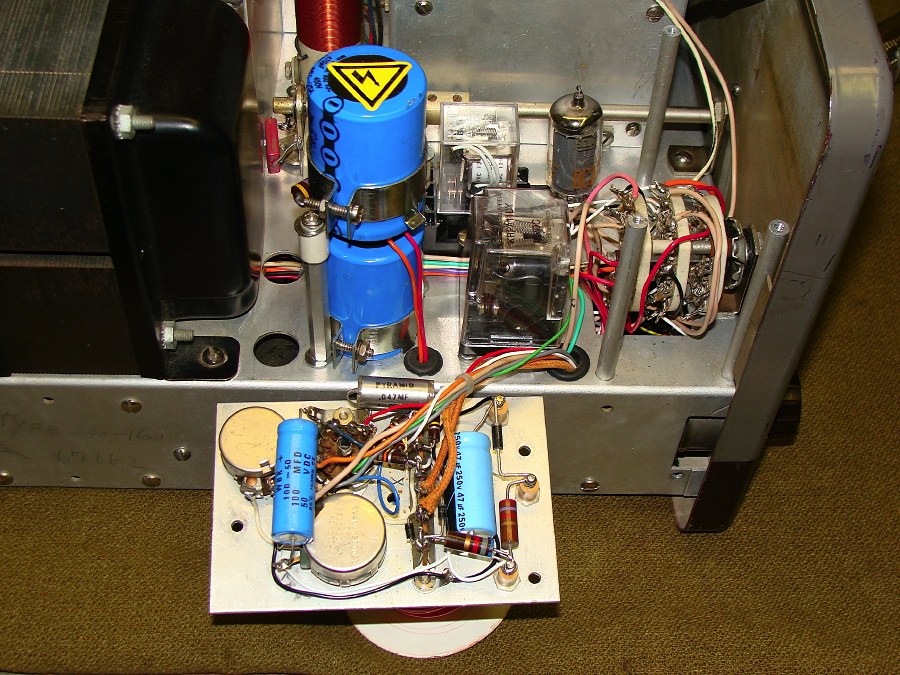
Photo 3 – Underside of keyer showing bias supply
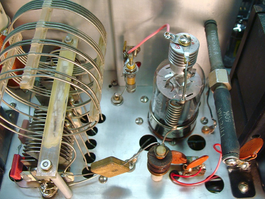
Photo 4 – RF Section
The
neutralization capacitor (a 2-14 pF glass piston trimmer) is soldered
to a two lug terminal strip and located on the rear shield between the
6146 and the tank coil. A screw hole (the original screw was
one of two for attaching the bracket supporting the tank switching
wafer) was enlarged to ¼ inch to accommodate an insulated feed-thru for
connection to the underside circuitry.
To the right of the 6146 there are the two 10 watt resistors in series
that constitute the high voltage bleeder.
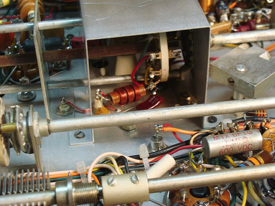
Photo 5 – Neutralizing and VFO Mods
The neutralization feed-thru is shown on the bottom of the chassis
where is comes through the wafer support bracket. A “nibbler”
was used to remove a small portion of the multiplier circuit shield so
that the neutralizing wire could directly enter the shielded area and
complete the neutralizing circuit.
Note the 160-volt zener diode for regulating the VFO that is located
toward the bottom center of the photo. An 8.5K 10 watt
dropping resistor for the zener is positioned on the inside wall of the
chassis.
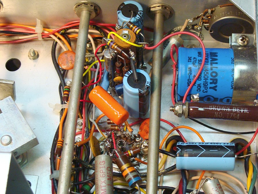
Photo 6 – Audio Section
The
470 uF 450 volt low voltage filter capacitor, located behind the audio
gain potentiometer, occupies the space formally held by T3, the
modulator driver transformer.
Below this capacitor is an 8.5K voltage dropping resistor for the VFO
zener diode.
The 12AX7 audio amplifier is located at the top center between the two
tuning shafts.
The 12AU7 phase inverter socket is located towards the bottom of the
photo.
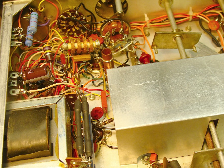
Photo 7 – Power Supplies and Wiring
The LV and HV rectifiers are encased in heat shrink tubing and mounted just to the right of LP2, the low voltage choke.
The 12 VDC supply is shown just above LP2.
The drive potentiometer modification resistors are shown in the upper left corner of the photo.
The rewiring effort used colored and numbered wires.