LIGHTNING PROTECTION New Myths & Old Realities As They Apply To Your Home And Your Station by
Bob McGraw - K4TAX |
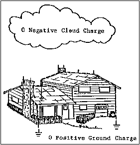
First some general comments about lightning. Lightning is a capricious, random and unpredictable event. Its' physical characteristics include current levels sometimes in excess of 400 kA, temperatures to 50,000 degrees F., and speeds approaching one third the speed of light. Globally, some 2000 on-going thunderstorms cause about 100 lightning strikes to earth each second. USA insurance company information shows one homeowner's damage claim for every 57 lightning strikes. Data about commercial, government, and industrial lightning-caused losses is not available. Annually in the USA lightning causes more than 26,000 fires with damage to property (NLSI estimates) in excess of $5-6 billion. The phenomenology of lightning strikes to earth, as presently understood, follows an approximate behavior:
Lightning effects can be direct and/or indirect. Direct effects are from resistive (ohmic) heating, arcing and burning. Indirect effects are more probable. They include capacitive, inductive and magnetic behavior. Lightning "prevention" or "protection" (in an absolute sense) is impossible. A diminution of its consequences, together with incremental safety improvements, can be obtained by the use of a holistic or systematic hazard mitigation approach, described below in generic terms. As previously stated, lightning has its own agenda; it is entirely capricious, random, and unpredictable. Man's attempts to fit lightning into a convenient box, with Codes and Standards to describe its behavior, are a best guess. The system of conventional lightning rods as commonly employed does represent the best method for providing a preferred pathway to ground. One very important aspect of ham radio antennas is the fact that they present themselves as being no different than lightning rods and therefore should be installed in the same manner and according to the standards used for lightning rod systems. Antennas are no different than any other air terminal. Second, lightning safety for group or large scale outdoor events is very difficult - maybe impossible - to accomplish. Injuries at a June 1998 rock concert at RFK stadium in Baltimore are a good example. Some 35,000 people were there. Lightning rods were there. Still, some 13 people were badly injured by incoming lightning. In July 1998 in Las Vegas NV, five firefighters were injured when lightning struck their fire truck. At a soccer match in the Republic of the Congo (October 1998), 11 members of the team were killed by lightning. Third, the myths about lightning persist:
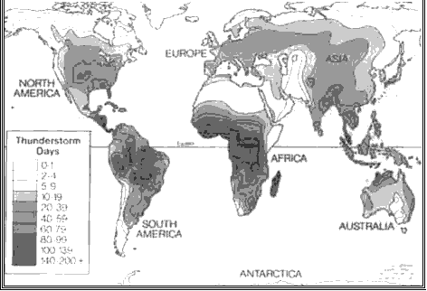
Lightning Strike Regions In World
THE PROBLEM On the military side, the Department of Defense Explosive Safety Board (DDESB) has reported 88 identifiable lightning-induced explosions in its records, with costs and deaths not calculated. DDESB was formed as a result of the Picatinny Arsenal incident (July 1926) which killed 14 people killed and cost $70 million. More recently in June 2001 at Buryatia Russia the lightninginduced munitions losses exceeded 20 million rubles. Here, fires burned for two days and were contained only after heavy rains. Three thousand people were evacuated, seventeen people were killed. How to mitigate the lightning hazard is the scope of this paper, with information presented in outline form. We begin with the assumption that Safety Is the Prevailing Directive. This leads to a prudent organizational policy which analyzes facilities and operations so as to identify lightning vulnerability. LIGHTNING BEHAVIOR When lightning strikes an asset, facility or structure (AFS) return-stroke current will divide up among all parallel conductive paths between attachment point and earth. Division of current will be inversely proportional to the path impedance, Z (Z = R + XL, resistance plus inductive reactance). The resistance term will be low assuming effectively bonded metallic conductors. The inductance, and related inductive reactance, presented to the total return stroke current will be determined by the combination of all the individual inductive paths in parallel. Essentially lightning is a current source. A given stroke will contain a given amount of charge (coulombs = amps x seconds) that must be neutralized during the discharge process. If the return stroke current is 50kA that is the magnitude of the current that will flow, whether it flows through one ohm or 1000 ohms. Therefore, achieving the lowest possible impedance serves to minimize the transient voltage developed across the path through which the current is flowing [e(t) = I (t)R + L di/dt)]. Why Should You Protect Your Home and Your Ham Station Against Lightning? This year 250 people in the United States will be killed by direct strikes of lightning. Another 500 will die in lightning caused fires. And at least 1500 persons will be injured by lightning which causes more damage, injuries and deaths each year than tornadoes, hurricanes or floods. The Lightning Protection Institute notes that 95% of today's homes are not protected against lightning surges. Most of the deaths and injuries would not have occurred if proper lightning protection equipment was installed. Lightning protection is designed for two objectives: it must provide a direct path for the lightning bolt to follow to ground, and it must prevent destruction or damage, injury or death, as it travels that path. The question: Copper or Aluminum? Both COPPER and ALUMINUM are approved by UL (Underwriters Laboratories) for the installation of Lightning Rod and Grounding Systems. There is little argument that copper is the material of choice because it is a better conductor of electricity. If aluminum is used in an installation, the cable has to be larger than the copper cable to conduct the same amount of current. Whenever possible, specify the use of copper in systems because it is the better material and is physically stronger and a better dollar value. The copper cable is smaller and thus less conspicuous and blends in better with most architecture, such as against brick walls and dark roofs. There are times when it is preferable to use aluminum materials. Since aluminum and copper are of dis-similar metals, they tend to corrode each other. Therefore, specify aluminum in the following exceptions:
Aluminum Lightning Protection equipment is approved by Underwriters Laboratories and has proved most satisfactory, but there are a few precautions to consider when using this material:
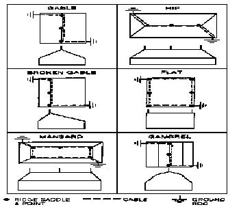
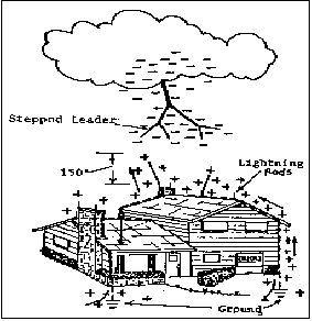
Typical Roof Bonding and Air Terminal Plans In all cases, any ham radio antenna or tower should be connected or bonded to the lightning protection system. Failure to properly comply with this method will produce a condition with a "step voltage" as a result of a nearby strike. In such event, the difference in potential will be developed between two or more ground points and thus current will flow between the two different potentials. In many cases, the radio equipment, via the AC neutral or supplied equipment ground, is in this path thus resulting in damage or destruction of the equipment.
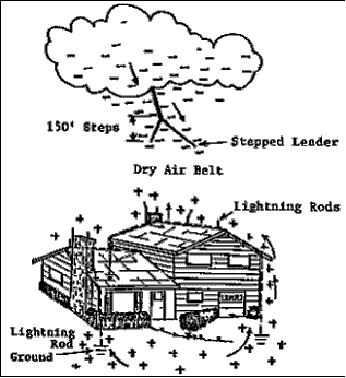
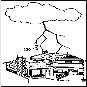
HOW A LIGHTNING PROTECTION SYSTEM WORKS
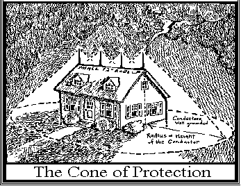
Figure 2 - Area Protected by Lightning Protection System
THE INS AND OUTS OF LIGHTNING PROTECTION Chances are, sooner or later, some part of your facilities will take a lightning strike. Preparation can help guard your expensive radio and computer equipment against damage or even destruction. Here you'll find some tips to help keep your station running smoothly. For Telco lines Several companies make surge suppressors intended for phone lines and ISDN lines. Some are in-line connectors with modular plugs. Others are hardwired at the demark point. The main methods of protection are Series and Shunt. Series devices typically plug directly into the line between the equipment and the demark attempting to block incoming surges before they reach your equipment. Shunt devices attach in parallel with the line. They try to direct the surge away from the equipment by providing a better path to ground. Some devices combine both methods of protection. Some Telco equipment manufacturers offer punch block solutions, such as the Siemon Pico Protector Module(5). These mount right to the punch block in place of bridging clips. Other modular devices are offered by several companies (such as Polyphasor(1), TrippLite(2), APC(3), and Panamax(4) that include ISDN and T1 solutions. (Note that the basic shunt device for POTS lines will work for an ISDN line when utilized into the U interface of a Zephyr.) For AC Power Lines Power conditioning and backup is fast becoming a requirement for many sensitive electronic devices including computers, audio processors, mission critical components, any device that relies on clean power for a CPU controlled device. Many of the home backup power devices even include RJ jacks for network and/or modem protection. Larger commercial types of power backup provide better protection that the smaller consumer devices. They have a better reaction time and offer better line filtering. Some of the very large installations tend to work in a "hot" mode where they are constantly online and commercial power is merely maintaining a charge on the batteries. A good surge suppressor should have some kind of an alarm system. This is because once a surge suppressor has done its job typically they are no longer any good and should be replaced. The technology behind some suppressors is that there are special components inside that get destroyed during a major lightning strike. The deadly force of the lightning is dissipated while components themselves are being destroyed and (ideally) not your equipment. If a series device fails "open" it will prevent power from passing to your device. A shunt device may fail as well but unless it shorts the power to ground you might not know this device is no longer protecting your equipment. This is the reason for some type of alarm or indicator informing the user of a failed status. Better surge suppressors have a longer useful life, but after so many lightning strikes (or one HUGE one) they may fail. Power back up devices or Uninterruptible Power Supplies (UPS) convert DC power supplied from batteries into AC power. Smaller units tend to provide just enough power to ride out a short duration power outage. The idea is to ride out these power outages till the power comes back or allow you enough time to gracefully shut down your equipment. More sophisticated UPS units have communication ports for monitoring their status so that equipment can automatically shut down should commercial power be lost. Small to medium UPS units tend to be preferred where there is a backup generator installed, such as a transmitter site. This works well when commercial power is lost and the UPS carries the load until the backup generator comes online. Things to Consider About UPS Devices Some of the smaller and older UPS units provide little to no surge suppression. Many people buy these devices thinking that they are also protected from power surges. Best to check the manufacturer's specifications. Commercial AC power out of the outlet is typically a pure sine wave. Most UPS devices do not produce a pure sine wave output but a modified alternating square wave. Most equipment with switching power supplies and analog power supplies can tolerate this modified sine wave but there is some equipment that cannot. For power solutions check out products from APC Inc.(3), Best Power(6), or TrippLite(2) (see references at end of this document). For RF Devices Suppression of lightning and surges for RF follows the same principles for dissipating surges as do Telco and power lines. Polyphasor1 has a full line of devices for RF that are well suited for coaxial lines with consideration to power levels and system frequencies. The ground system at the base of a tower should be bonded to all other grounds associated with the system. This includes the AC power ground at the service entrance, any Telco ground which should be connected at the AC power ground point, any cable TV or satellite antenna systems, well pumps should be bonded back to the AC power ground and therefore there is no reliance on the AC neutral. One other area of concern is the vertical mast protruding through or from the top of a tower. A separate bond strap, flexible in nature if there is a rotating system, should connect the mast to the tower at the top of the tower. Typically the vertical mast should be fitted with a pointed rod of some 0.5 inches in diameter protruding from the extreme uppermost point. This then forms a proper air terminal for the structure. GROUNDING Many ham antenna installations use a very unscientific and poorly planned ground system. Typically the idea of more grounds thus more driven ground rods and attachment points the better. This is not necessarily correct in that one important aspect is often omitted in the ground system. Proper grounding is essential to maintaining equipment safety. Many facilities employ a grounding system that is very intricate. The idea is to provide a central grounding point for all equipment to maintain a common ground. RF lines entering buildings from antenna structures would typically have copper strap bonded to the outer conductor and shunted to the common ground to help divert the major surge away from the equipment. Equipment racks in transmitter sites are also tied into this common ground system to maintain the same potential. Dedication to proper AC and ground wiring techniques can ensure minimal risk to one's equipment due to a surge and also can reduce incidents of ground loops and hum in your facility. The grounding system must address low earth impedance as well as low resistance. A spectral study of lightning's typical impulse reveals both a high and a low frequency content. The high frequency is associated with an extremely fast rising "front" on the order of 10 microseconds to peak current. The lower frequency component resides in the long, high energy "tail" or follow-on current in the impulse. The grounding system appears to the lightning impulse as a transmission line where wave propagation theory applies. A single point grounding system is achieved when all equipment within the structure(s) are connected to a master bus bar which in turn is bonded to the external grounding system at one point only. Earth loops and differential rise times must be avoided. The grounding system should be designed to reduce ac impedance and dc resistance. The shape and dimension of the earth termination system is more important a specific value of the earth electrode. The use of counterpoise or "crow's foot" radial techniques can lower impedance as they allow lightning energy to diverge as each buried conductor shares voltage gradients. Ground rings around structures are useful. They should be connected to the facility ground. Exothermic (welded) connectors are recommended in all circumstances. Cathodic reactance should be considered during the site analysis phase. Man-made earth additives and backfills are useful in difficult soils circumstances. They should be considered on a case-by-case basis where lowering grounding impedances are difficult an/or expensive by traditional means. Regular physical inspections and testing should be a part of an established preventive maintenance program. A considerable part of lightning's current responds horizontally when striking the ground: it is estimated that less than 15% of it penetrates the earth (Sandia Labs, 1993)(11). As a result, low resistance values (25 ohms per NEC) are less important than volumetric efficiencies. Corrosion and cathodic reactance issues should be considered during the site analysis phase. Where incompatible materials are joined, suitable bi-metallic connectors should be adopted. Joining of aluminum down conductors together with copper ground wires is a typical mistake. Good station grounding techniques are essential to minimize the damage of a lightning strike. With the proper grounding of your station equipment and AC power ground, you stand a much better chance of surviving a lightning strike. Instead of losing the entire station, you may only lose one or two specific items. With adequate surge protection, the damage to the specific item(s) will ideally be minimal (if any). For more information on facility grounding and techniques refer to the references listed below. Old Fashioned Tricks For years, computer technicians have talked of tying knots (usually three) in the power cords of the computers as lightning protection. They report that in really bad lightning strikes, the power cords with knots were totally destroyedbut the computer was perfectly fine. The only cost incurred was for a new power cord. Not bad lightning protection for $3.99! Others have used ferrite beads and looped the cords through these. Some people report the same results doing the same trick with phone lines! Surge protection devices (SPD aka transient limiters) may shunt current, block energy from traveling down the wire, filter certain frequencies, clamp voltage levels, or perform a combination of these tasks. Voltage clamping devices capable of handling extremely high amperages of the surge, as well as reducing the extremely fast rising edge (dv/dt and di/dt) of the transient are recommended. Ordinary fuses and circuit breakers are not capable of dealing with lightning-induced transients. Surge suppressors should be installed with minimum lead lengths to their respective panels. Under fast rise time conditions, cable inductance becomes important and high transient voltages can be developed across long leads. In all instances, use high quality, high speed, and self-diagnosing protective components. Transient limiting devices may use a combination of arc gap diverters or metal oxide varistor or silicon avalanche diode technologies. Hybrid devices, using a combination of these techniques, are preferred. IEEE 1100 gives good guidance here. Uninterrupted Power Supplies (UPSs) provide battery backup in cases of power quality anomaliesbrownouts, capacitor bank switching, outages, lightning, etc. UPSs are employed as back-up or temporary power supplies. They should not be used in place of dedicated SPD devices. Correct IEEE Category A installation configuration is: AC wall outlet to SPD to UPS to equipment. Know your clamping voltage requirements. Confirm that your vendor's products have been tested to rigid ANSI/IEEE/ISO9000 test standards. Avoid low-priced, bargain products which proliferate the market (caveat emptor). Recommendations Put the surge protection circuits close to the equipment. If possible, tie the ground of the Telco line suppression unit to the common ground or the chassis of the protected equipment. Use a very short lead (4-6") between the suppression module and the equipment. Establish a common ground in your facility and make the attempt to route all your grounds to that point. Choose power conditioning/UPS units suited for your application. Make sure they are rated to handle the equipment they will power. Check for features and options you will need. Verify the surge protection of the device and make sure it is adequate. Frequently check these units for faults, especially after a storm. Buy the best your money can buy. Don't forget that all ham radio, TV, telephone and cable related equipment must deal with a "double whammy". Lightning can come from either the power line or the phone line/cable line (sometimes BOTH!). For example: lightning can come from the phone line and try to work its way to the power line ground (or the other way around). In the process, it will usually destroy the gear and neighboring equipment! Protect all lines into your equipment. Try tying knots in your cords. Add the ferrite beads. Couldn't hurt to try.
LIGHTNING PROTECTION DESIGNS Mitigation of lightning consequences can be achieved by the use of a detailed systems approach, described below in general terms. Air Terminals: Since Benjamin Franklin's day, lightning rods have been installed upon ordinary structures as sacrificial attachment points, intending to conduct direct flashes to earth. This integral air terminal design may not provide protection for electronics, explosives, or people inside modern structures because of flashover and transfer impedance. Inductive, magnetic and capacitive coupling from intended lightning conductors can result in significant voltages and currents on unintended interior power and signal conductors. Lightning will follow the path of least impedance to ground. Overhead shield wires and mast systems located above or next to the structure are suggested by the US Air Force (AFI 32-1065) and by NASA (STD E0012E) as preferred alternatives to rods in many circumstances. These designs are termed indirect air terminals. Such methods are intended to collect lightning above or away from the sensitive structure, thus avoiding or reducing flashover attachment of unwanted currents and voltages to the facility and equipments. Unconventional air terminal designs which claim the elimination or redirecting of lightning (charge transfer or dissipater arrays) or lightning preferential capture (early streamer emitters) deserve a very skeptical reception. Peer-reviewed studies which have dismissed these claims include: NASA/Navy Tall Tower Study, 1975; R.H. Golde "Lightning" 1977; FAA Airport Study 1989; T. Horvath "Computation of Lightning Protection" 1991; D. MacKerras et al, IEE Proc-Sci Meas. Technol, V. 144, No. 1 1997; National Lightning Safety Institute "Royal Thai Air Force Study" 1997; A. Mousa "IEEE Trans. Power Delivery, V. 13, No. 4 1998 among others. Lightning Rods: In Franklin's day, lightning rods conducted current away from buildings to earth. Lightning rods, now known as air terminals, are believed to send Streamers upward at varying distances and times according to shape, height and other factors. Different designs of air terminals may be employed according to different protection requirements. For example, the utility industry prefers overhead shielding wires for electrical substations. In some cases, no use whatsoever of air terminals is appropriate (example: munitions bunkers). Air terminals do not provide for safety to modern electronics within structures alone. Additional and specific steps as outlined in this writing is required. Air terminal design may alter Streamer behavior. In equivalent e-fields, a blunt pointed rod is seen to behave differently than a sharp pointed rod. Faraday Cage and overhead shield designs produce yet other effects. Air terminal design and performance is a controversial and unresolved issue. Commercial claims of the "elimination" of lightning deserve a skeptical reception. Further research and testing is on-going in order to understand more fully the behavior of various air terminals. Downconductors: Downconductors should be installed in a safe manner through a known route, outside of the structure. Gradual bends (min. eight inch radius) should be adopted to avoid flashover problems. Building steel may be used in place of down conductors where practical as a beneficial part of the earth electrode subsystem. Shielding is an additional line of defense against induced effects. It prevents the higher frequency electromagnetic noise from interfering with the desired signal. It is accomplished by isolation of the signal wires from the source of noise. Bonding: This assures that unrelated conductive objects are at the same electrical potential. A very important point: Without Bonding, lightning protection will not work. All metallic conductors entering structures (ex. AC power lines, gas and water pipes, data and coaxial signal lines, conduits and piping, roll up doors, personnel metal door frames, hand railings, etc.) should be electrically referenced to the same ground. Connector bonding should be welded and not mechanical wherever possible, especially in below-grade locations, since mechanical bonds are subject to corrosion and physical damage. Frequent inspection and resistance measuring (maximum 5 milliohms per FAA and National Weather Service standards) of connectors to assure continuity is recommended.
CONCLUSION Lightning has its own agenda and may cause damage despite application of best efforts, including those described above. Any comprehensive approach for protection should be site-specific to attain maximum efficiencies. In order to mitigate the hazard, systematic attention to details of grounding, bonding, shielding, air terminals, surge protection devices, maintenance, and employment of risk management principles is recommended. '
RECOMMENDED GROUNDING GUIDELINES Prominent lightning engineers and major technical codes and standards agree as to proper grounding guidelines. Here are summaries of those generally accepted designs. 1. From Golde, Lightning, Academic Press, NY, 1977, vol. 2, chapter 19 by H. Baatz, Stuttgart, Germany, p. 611: "Equalization of potentials should be effected for all metallic installations. For lightning protection of a structure it is of greater importance than the earthing resistance... The best way for equalization of potentials utilizes a suitable earthing system in the form of a ring or foundation earth. The down conductors are bonded to such a ring earth; additional earth electrodes may be unnecessary" 2. From Sunde, Earth Conduction Effects in Transmission Systems, Van Nostrand, NY, 1949, p. 66: "Adequate grounding generally requires that the resistance of the ground, at the frequency in question, be small compared to the impedance of the circuit in which it is connected. By this criterion, it may be permissible in some instances to have a ground of high resistance, several thousand ohms, as in the case of "electrostatic" apparatus ground, the impedance to ground of insulated apparatus cases being ordinarily quite high. In other [situations], however, a resistance of only a few ohms may be required for effective grounding." 3. From Horvath, Computation of Lightning Protection, Research Studies Press, London, 1991, p. 20: "The earthing of the lightning protection system distributes the lightning current in the soil without causing dangerous potential differences. For this purpose the most effective earthing encloses the object to be protected. The potential increases on the earthing and on all earthed metal parts of the object relative to the zero potential at a distant point. It may reach a very high value but it does not cause any danger if the potential differences inside the object to be protected are limited. Potential equalization is realized by the bonding of all extended metal objects." 4. From Hasse, Overvoltage Protection of Low Voltage Systems, Peter Peregrinus Press, London, 1992, p. 56. ''Complete lightning protection potential equalization is the fundamental basis for the realization of internal lightning protection; that is the lightning overvoltage protection for the electrical and also the electronic data transmission facilities and devices in buildings. In the event of a lightning stroke, the potential of all installations in the affected building (including live conductors in the electrical systems with arrestors) will be increased to a value equivalent to that arising in the earthing system -- no dangerous overvoltages will be generated in the system Nowadays lightning protection potential equalization is considered indispensable. It ensures the connection of all metal supply lines entering a building, including power and communication cables, to the lightning protection and earthing system by direct junctions across disconnection spark gaps, or arrestors in the case of live conductors." 5. From IEEE Emerald Book, Powering and Grounding Sensitive Electronic Equipment, IEEE Std 1100-1992, IEEE, NY, 1995, p. 216: "It is important to ensure that low-impedance grounding and bonding connections exist among the telephone and data equipment, the ac power system's electrical safety-grounding system, and the building grounding electrode system. This recommendation is in addition to any made grounding electrodes, such as the lightning ground ring. Failure to observe any part of this grounding requirement may result in hazardous potential being developed between the telephone (data) equipment and other grounded items that personnel may be near or might simultaneously contact." 6. From International Standard IEC 1024-1, Protection of Structures Against Lightning, International ElectroTechnical Commission, Geneva, 1991, p. 23: "In order to disperse the lightning current into the earth without causing dangerous overvoltages, the shape and dimensions of the earth-termination system are more important than a specific value of the resistance of the earth electrode. However, in general, a low earth resistance is recommended. From the viewpoint of lightning protection, a single integrated structure earth termination is preferable and is suitable for all purposes (i.e. lightning protection, low voltage power systems, telecommunication systems). Earth termination systems which must be separated for other reasons should be connected to the integrated one by equipotential bonding" 7. From FAA-STD-019b, Lightning Protection, Grounding, Bonding, and Shielding Requirements for Facilities, Federal Aviation Administration, Washington DC, 1990, p. 20: "The protection of electronic equipment against potential differences and static charge build up shall be provided by interconnecting all non-current carrying metal objects to an electronic multi-point ground system that is effectively connected to the earth electrode system." 8. From MIL-STD-188-124B, Grounding, Bonding and Shielding, Department of Defense, Washington DC, 1992, p. 6 and p. 8: "The facility ground system forms a direct path of known low voltage impedance between earth and the various power and communications equipments. This effectively minimizes voltage differentials on the ground plane which exceed a value that will produce noise or interference to communications circuits." (p.6) "The resistance to earth of the earth electrode subsystem should not exceed 10 ohms at fixed permanent facilities." (p. 8) 9. From MIL-STD-1542B (USAF), Electromagnetic Compatibility and Grounding Requirements for Space Systems Facilities, Department of Defense, Washington DC, 1991, p. 19: "This Standard, MIL-HDBK-419, and MIL-STD-188-124 do not recommend the use of deep wells for the achievement of lower impedance to earth. Deep wells achieve low dc resistance, but have very small benefit in reducing ac impedance. The objective of the earth electrode subsystem is to reduce ac and dc potentials between and within equipment. If deep wells are utilized as a part of the earth electrode subsystem grounding net, the other portion of the facility ground network shall be connected to them." 10. From National Electrical Code, NEC-70-1996, National Fire Protection Association, Quincy MA, 1996, Article 250 - Grounding, p. 120 & p. 144: "Systems and circuit conductors are grounded to limit voltages due to lightning, line surges, or unintentional contact with high voltage lines, and to stabilize the voltage to ground during normal operation. Equipment grounding conductors are bonded to the system grounded conductor to provide a low impedance path for fault current that will facilitate the operation of overcurrent devices under ground-fault conditions." (p. 120) "Metal Underground Water Pipe. A metal underground water pipe in direct contact with the earth for 10 ft. (3.05 m) or more (including any metal well casing effectively bonded to the pipe) and electrically continuous (or made electrically continuous by bonding around insulating joints or sections or insulating pipe) to the points of connection of the grounding electrode conductor and the bonding conductors. Continuity of the grounding path or the bonding connection to interior piping shall not rely on water meters or filtering devices and similar equipment. A metal underground water pipe shall be supplemented by an additional electrode of a type specified in Section 250-81 or in Section 250-83. The supplemental electrode shall be permitted to be bonded to the grounding electrode conductor, the grounded service-entrance conductor, the grounded service raceway, or any grounded service enclosure." (p. 145) 11. From MIL-HDBK-419A, Grounding, Bonding, and Shielding for Electronic Equipments and Facilities, Department of Defense, Washington DC, 1987, p. 1-2, p. 1-6, p.1-102 and p. 1-173: "The value of 10 ohms earth electrode resistance recommended in Section 1.2.3.1a represents a carefully considered compromise between overall fault and lightning protection requirements and the estimated relative cost of achieving the resistance in typical situations." (p. 1-2) "At fixed C-E facilities, the earth electrode subsystem should exhibit a resistance to earth of 10 ohms or less." (p.1-6) "All metallic pipes and tubes (and conduits) and their supports should be electrically continuous and are to be bonded to the facility ground system at least at one point." (p. 1-102) "Water pipes and conduit should be connected to the earth electrode subsystem to prevent ground currents from entering the structure." (p. 1-173)
EDUCATION Lightning safety should be practiced by all people during thunderstorms. Preparedness includes: get indoors or in a car; avoid water and all metal objects; get off the high ground; avoid solitary trees; stay off the telephone. If caught outdoors during nearby lightning, adopt the Lightning Safety Position (LSP). LSP means staying away from other people, taking off all metal objects, crouching with feet together, head bowed, and placing hands on ears to reduce acoustic shock. Measuring lightning's distance is easy. Use the "Flash/Bang" (F/B) technique. For every count of five from the time of seeing the lightning stroke to hearing the associated thunder, lightning is one mile away. A F/B of 10 = 2 miles; a F/B of 20 = 4 miles, etc. Since the distance from Strike A to Strike B to Strike C can be as much as 5-8 miles. Be conservative and suspend activities when you first hear thunder, if possible. Do not resume outdoor activities until 20 minutes has past from the last observable thunder or lightning. Organizations should adopt a Lightning Safety Policy and integrate it into their overall safety plan.
CODES & STANDARDS The marketplace abounds with exaggerated claims of product perfection. Frequently referenced codes and installation standards are incomplete, out dated and promulgated by commercial interests. On the other hand IEC, IEEE, MIL-STD, FAA, NASA and similar documents are supported by background engineering, the peer-review process, and are technical in nature.
SUMMARY It is important that all of the above subjects be considered in a lightning safety analysis. There is no Utopia in lightning protection. Lightning may ignore every defense man can conceive. A systematic hazard mitigation approach to lightning safety is a prudent course of action.
This article will be published in "Proceedings
of the 2003, Southeastern VHF Society Conference. pp 101 - 117, ARRL |