All these antennas are simple, low tech and inexpensive. This is not a brag page. I've done nothing new or special here. I put this up mostly to document the progression of the antennas at the current QTH and to have an easy way to answer questions from other about my antennas.
December 2005
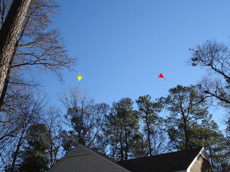
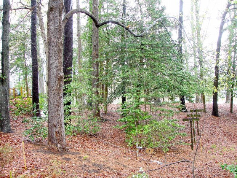
The two dipoles, 160-meter marked with yellow and the 80/75-meter marked with red.
The front half of the 160-meters dipole is marked with yellow (lower mark is the center insulator). The leg crosses the 80/75-meter dipole (marked in red). The 160-meter wire is about 5-10 feet lower than the 75-meter dipole. The center of the 80/75-meter dipole is at 75-80 feet, so the 160-meter dipole should be around 60-70 feet high.
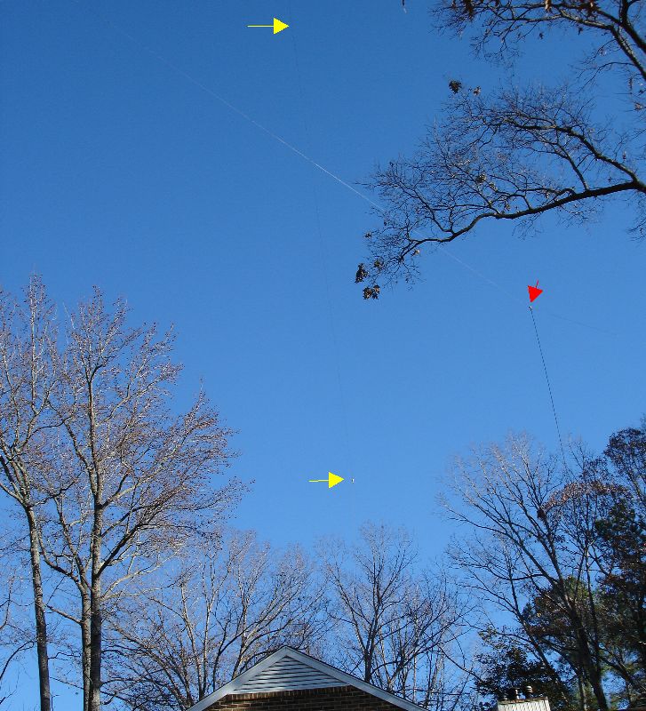
The back leg of the 160-meter dipole enters the trees at the yellow mark. From there it goes through two more trees, the last one at the edge of the lake.
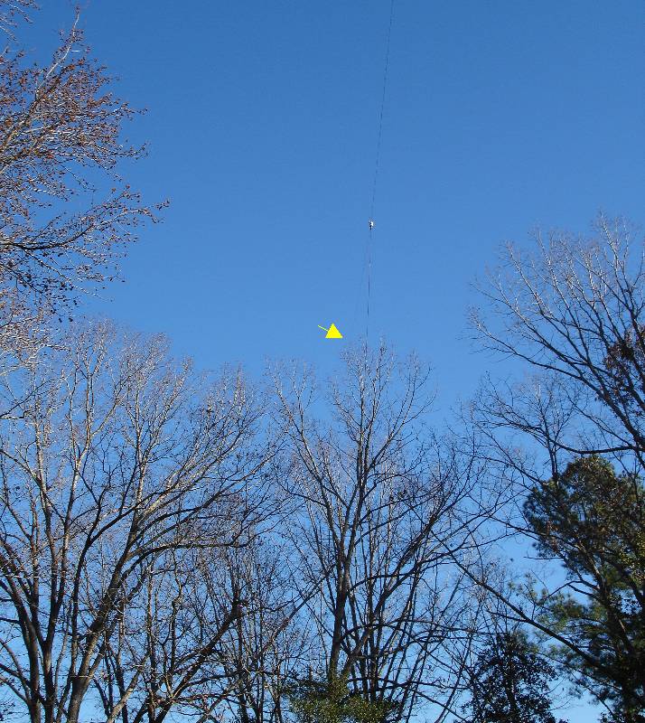
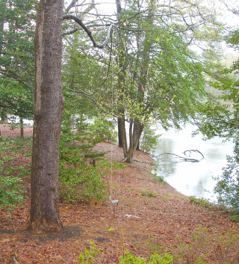
Another view of the previous from a different angle.
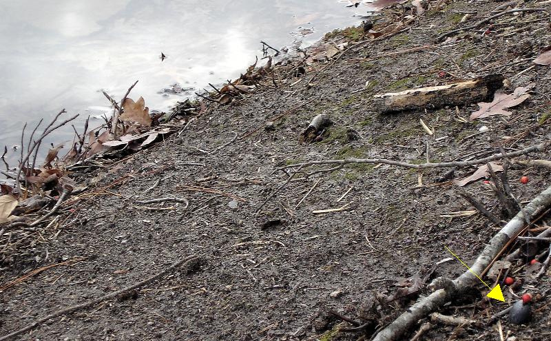
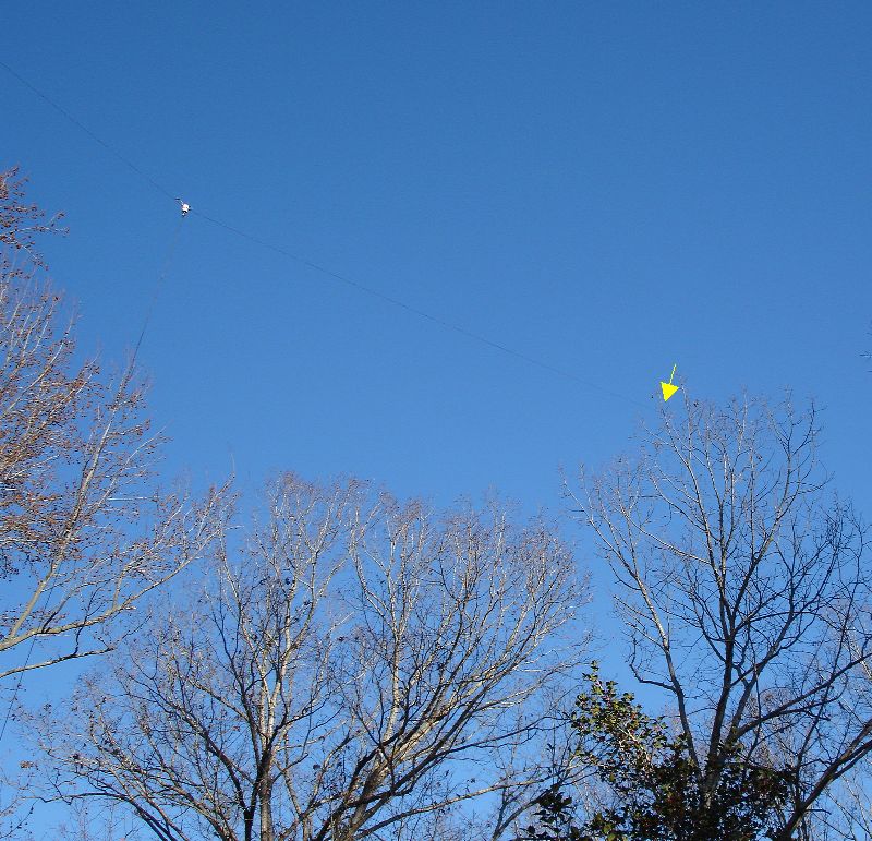
I used a sling shot to get the wires up in the trees. The back half of the 160-meter dipole needed to go over three trees. On the very first shot with sling shot, I made it over all three trees and the sinker (yellow marker) landed a foot or so from the edge of the lake. Some days you get lucky!
Update: The 160-meter dipole came down in December of 2012. I had a Christmas star of lights hanging from it. The extra weight broke one of the wires. I have yet to put it back up since I've operated little on 160-meters in recent years. If I put another antenna up for 160-meters, it will likely be an Inverted-L.
Receiving Antenna Added December 2006
Below are some shots of the K9AY receiving loop I added in December 2006. It is switchable in four directions, NE, SW, SE, NW. Using a fixed value of terminating resistance, 470 Ohms, it shows 15-25 dB front-to-back (F/B) ratio on 80/75-meters depending on the path, time of day, location of the station etc.
The F/B ratio is even higher on 160-meters and the top end of the broadcast band, approaching 25-30 dB in some cases. I've used it mostly on 75-meters and it has proved invaluable in working SSB DX. Often a DX station cannot be copied on the dipole, but switching to the K9AY loop makes them Q5. Even if the station is copied on the dipole, the copy on the loop is much more comfortable. I was even able to work PE1MPH and F6AKQ on AM at 3705 kHz in April! (Update January 2009: I've worked F6AQK and numerous other European AMers many times over the last few winters). I would never have been able to copy them without the loop.
Update January 2009
I've been using the K9AY a good bit on 160-meters too. It works well for stateside AM contacts. Some of the more northern New England stations can be a tough copy some nights on the 160-meter dipole. But with the K9AY, I can usually hear all of them. In some cases, with the K9AY, the copy becomes "arm chair." I've also found the K9AY and the Beverage (below) can be useful for daytime operation. I can often hear New England stations early in the afternoon with the two receiving antennas. I cannot copy (I can tell a signal is there but no intelligible audio) them using the dipole, or it's very tough copy. I've talked to WA1HLR as early as 1PM ET in the winter months on 75-meters. That's a path of over 600 miles. Tim has very good ears because he has very high directional antennas. This made the two-way path work.
Here's a view of the loop looking north. It's basically two triangle-shaped loops that feed a switch box. The loops are 85 feet in total length. As configured, the tops of the loops are at about 25-30 feet above the ground. The footprint is about 15 feet on each side of center, for a total of 30 feet. This amounts to a rather small antenna for directional receive on the low bands.
A view looking towards the Northeast, right into Europe. Switching the loop to the Northeast often aids in the reception of some of the New England AM stations - especially if there is QRM or QRN to the Southwest or even Southeast. On the other hand, switching to the Southwest REALLY helps in hearing some of the West Coast AMers and Hawaii and East Kiribati on SSB.
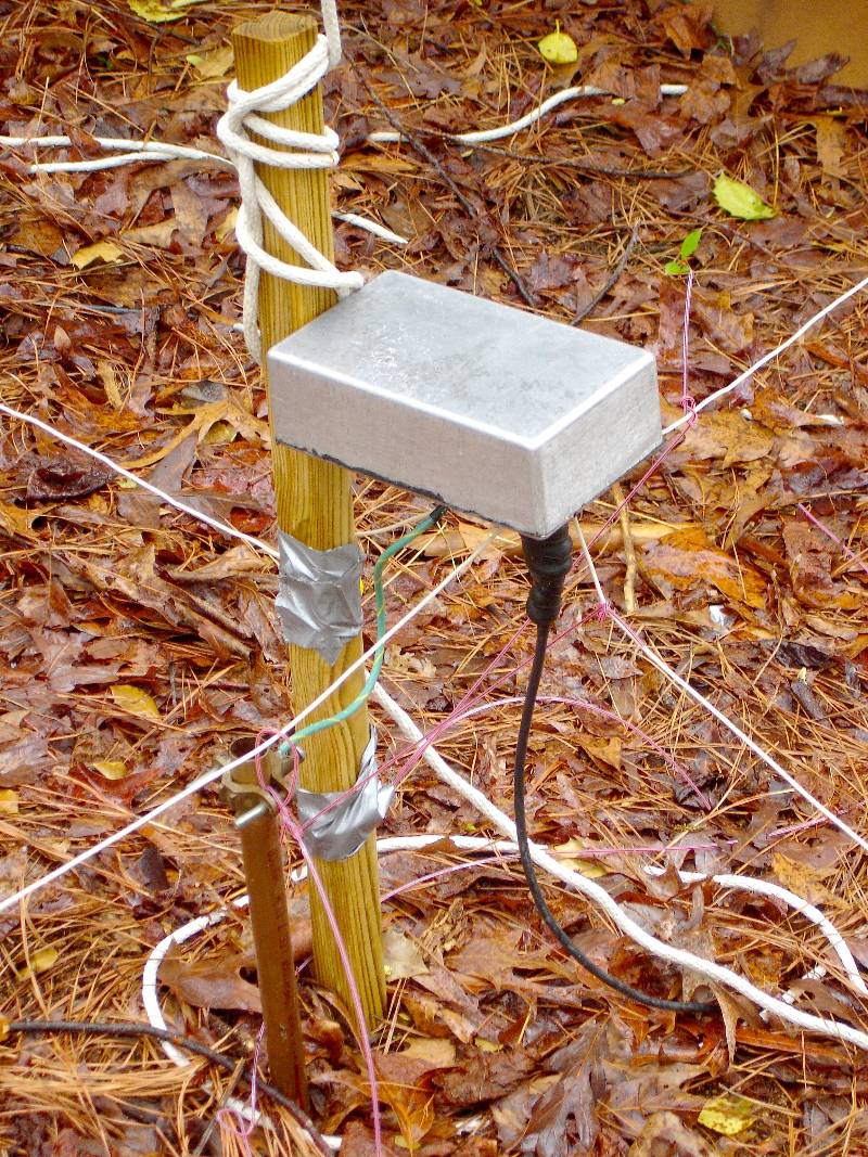
Above is a close-up of the switch box. The box is controlled from inside the shack and allows for selection of the four directions. It houses two relays, a matching transformer and the terminating resistor. Control voltages for the relay are fed down the coax.
Beverage Antenna Added January 2009
Below is a shot of part of the Beverage I added in January 2009. It's rather short, only about 220-feet long, but it does provide some directivity on 80-meters. It's oriented for best reception to the Northeast. Often, I can hear a stations better with the Beverage than with the K9AY in its Northeast position. The improvement seems to be more noticeable on eastern European stations and the Russians. On 40-meters, the Beverage is about 1.5 wavelengths long, so it shows much more directivity.

Update September 2009
I've added a second Beverage that is phased with the first in an end-fire configuration. The phasing line that feeds the rear Beverage is used with a 180-degree phase-reversing transformer to provide proper phasing across at least 160, 80, and 40-meters. This sort of phasing is an old technique that has been around since at least the early 1960's, but has recently been discovered by the amateur radio world. There are even what appear to be some bogus claims on inventing or introducing such techniques with silly sounding names like Echelon-Log Beverages and Cross-Fire Phasing. These sound fancy, but are just copies of work done by others decades before. These are no more valid than copying a Yagi design and giving it a name like Passive Coupling Directive Antenna Array (PCDAA). Any intelligent person would laugh you out of the room. I've used commercial directional receiving antennas in the 1980's that used the above phasing configuration (based on patents dating to the early and mid-1960s). Further, this arrangement of two Beverage antennas was developed and documented by the Bell System in the mid/late 1920s. Read the Bell System Technical Journal from April 1929, "The Receiving System for Long-Wave Transatlantic Radio Telephony." As you can see, there's really no need for made up terms like stagger unless you are describing a drunk (maybe that's where these wacky names come from).
Adding the second Beverage really improved the receive capability. The Beverages are now always superior to the K9AY on signals from the Northeast - signals are usually a little stronger (especially under lower angle conditions) and the noise is reduced. It's amazing how quiet the 80-meter band can be sometimes when using this antenna.
The reason why is evident when comparing the antenna patterns of the two antennas on 80-meters (below). Notice that the Beverages (in red) have a much more narrow lobe in the azimuthal pattern and less high angle response on the elevation plot. Both of these pattern differences result in less noise received. Also the tighter backside pattern of the Beverages is great for reducing some stateside QRM. I often see USA stations drop 20 dB or more in signal strength when switching from the dipole to the Beverages.
The Beverages also drastically reduce thunderstorm noise emanating from the South and West of my location. Take a listen to the audio clip at the link below. It was recorded on 80-meters in September 2010 while switching between a dipole and the Beverages. It almost sounds like the thunderstorm static is switched off when listening on the Beverages. Keep in mind that OK2RZ had a very strong signal, something like 5/9+10-15. Still the late summer static on the dipole is quite noticeable. On the Beverages it is all but gone!
Dipole Versus Beverages
Now listen to what the Beverage does on a weaker signal. At the link below you will first hear UR3QCW on 80-meters quite clearly. This is reception on the Beverages. You will hear UA3 clearly. Then as he starts to say QCW, you'll hear mostly static. This is reception on the dipole. I switch back and forth between the dipole and Beverages a few more times in the clip. It is safe to say it would have been much more difficult to pull out UA3QCW using the dipoles. However, copy is quite easy on the Beverages.
UA3QCW on 80-Meters
None of this should be surprising. The engineers at Bell knew this in the 1920s, as can be seen from a one sentence summary from the report cited above:
When this type of array is properly
designed, the reduction in directional receptivity due to the
array is principally in the back-end direction.
The subject array was two Beverage antennas (called wave antennas in the report) in an end-fire configuration (called a longitudinal array in the report). The array was being compared to a single Beverage. The boys at Bell had it all figured out in the 1920s!
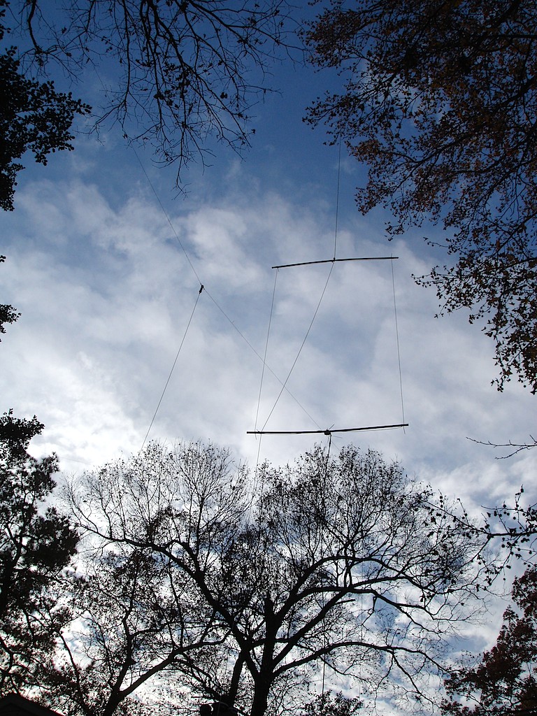
40-Meter Dipole Added March 2009
I wanted to get something up for 40-meters since the fall of 2008. Finally, after some failed attempts, I got up a 40-meter dipole at the beginning of March 2009. It was right next to the lake and up about 70 feet. The view below is looking Northeast. In the short time it was up, I worked about 40 countries on 40-meter SSB.

You may wonder, why I would take down such a nicely placed antenna. I asked myself that question a few times too while I was fighting to put up the antennas below!
40-Meter Two-Element Delta-Loop Array Added April 2009
With the broadcast stations departing from 7100 to 7200 kHz in late March, that portion of the band became even more busy. The Europeans loved it since they were blasted far more by the BC stations than we in the USA. I got to thinking of putting up some sort of directional array, especially to beam to Europe. Antenna dimensions are much smaller on 40-meters than for the band I used most often in recent years, 80-meters. Also, even 60-foot high antenna on 40-meters produces a respectable lower take-off angle. Some cajoling by a fellow ham prompted me to go for it. After much work, I wound up with a two-element delta loop array in the same location used previously by the dipole.

I went with the delta loops because I could not fit two dipoles in the space available without really getting into the trees. The array is parasitic with one loop driven and the other tuned as a reflector by a shorted coaxial cable stub. The driven and tuned elements can be switched, so the array can beam Northeast or Southwest. Modeling shows about 4 dB forward gain (compared to a dipole) and a 20-30 dB front-to-back ratio (F/B). See the modeled pattern plots below.
Only a few on-the-air tests have been done to date, and the F/B showed in the 20-30 dB range. More testing over various paths and distances will be needed to tell the whole story, but so far, so good.
Right: Elevation Pattern
Update June 2009
Extensive testing over the past few months on 40-meters has repeatedly produced reports of 15-25 dB F/B. The amount depends on the time of day and distance to the other station. Even on USA stations within 300-400 miles, I've seen well over 20 dB and sometimes 30 dB F/B. On the same station, only 15-20 minutes later, I might only see 10 dB. There is far less variation on more distant stations (averages around 20 dB F/B). I've even received a few reports of over 30 dB F/B out of Europe. These must be occurring when the incoming incoming signal is around the perfect angle to hit the null of the back side of the array (look at the elevation pattern plot at around 35 degrees). Or someone's S-meter is off!!
Update August 2009
I've worked 136 countries on 40 meters since March 2009 - all on phone. This was done with what I would call casual operation. I don't use clusters or spots to find new ones, and I don't operate in contests. I pretty much work what comes along. Bottom line, this antenna works! I get great reports with it and I can hear stuff many other stations cannot.
Update December 2011
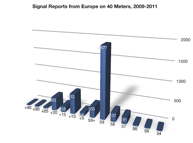
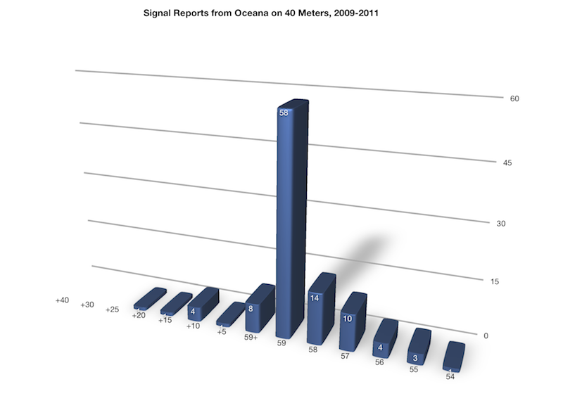
I pulled signal reports from the 3900 SSB contacts I've made with European stations since 2009. As you can see, the delta loops produce a 5-9 or better report far more often than not.
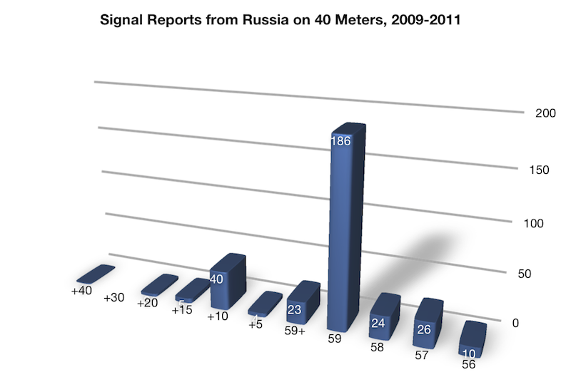
Let's look at a little tougher path - contacts to far eastern Europe, namely Russia. Here the data is from 332 contacts. Once again, the delta loops usually produce 5-9 or better report.
Although the data set is smaller (a little over 100 contacts), the loops still most often produce 5-9 reports into the Pacific. Not surprisingly, there aren't as many 59+xx reports. Most of these contacts were with VKs. The paths for all contacts was split about 1/3 for long path and 2/3 for short path.
Although these numbers do not qualify as statistics, they do show some pretty prominent trends and are another way of looking at the performance of the delta loops. A side-by-side comparison with a reference antenna (dipole or vertical) would be much more informative.
Update 2014: I've tuned this array up to operate on 20 and 15 meters using a typical CLC T-type tuner. Without the tuner, the array shows resonance on 20, 15 and 10 meters with an impedance near 50 Ohms and pretty low reactance. I haven't figured out or modeled the pattern for any band yet (one of these days). That said, in limited operating since 2012 (with most of it occurring since 2013) and running just 100 watts, I've managed to work 123 DXCC on 20 meters phone and 111 DXCC on 15 meter phone. This just shows that nearly anything will work when the higher HF bands are open.
10-Meter Rectangular Loop Added November 2011
The sunspots have returned and the activity on 10 meters really took off in the fall of 2011. To join in on the fun, I put up a quick and dirty dipole. Since I already had an unused rope in a tree, I hung the dipole vertically. Although this antenna is about as close to a "no-gain" antenna as you can get, when 10 is open you can work the world with almost any antenna. During the CQWW SSB contest, I worked 50 DXCC entities in about 1.5 hours of casual operating (spot and pounce). I was running 100 watts.
But I wanted to put up something better, yet still expend little effort. The rectangular full-wave loop seemed to be a good choice. I could use the same single rope as used with vertical dipole to support it. The loop has a 50 Ohm feedpoint and it has 1-2 dB gain over a horizontal dipole. The kicker is that it has 7-8 dB gain over the vertical dipole.
Azimuth Radiation Patterns (Red: Rectangular Loop, Dashed: Vertical Dipole)
Elevation Radiation Patterns (Red: Rectangular Loop, Dashed: Vertical Dipole)
It took about and hour to construct and raise. With a little trimming it was tuned up and ready to go. This antenna is no Yagi killer. But for a small, single support antenna (could be mounted on a mast too), it's about as good as it gets. All you need is about 36 feet of wire, two spacers (I used 0.75 inch PVC pipe) and some cable ties or electrical tape. I used a bead balun at the feedpoint.
10-Meter Four-Element Yagi Added March 2012
The all wire antenna spell has been broken. A 4-element Yagi (aluminum tubing) was installed for 10 meters. I guess it can exist with all the other wire antennas! Update: I've been using the 10-meter loop during most of 2013. A tree branch fell and busted one of the elements of the Yagi. I've been too lazy to fix it. :-(
20-Meter Rectangular Loop Added May 2013
I stumbled into some good contacts and/or conditions on 20-meters in March of 2012. I was tuning up the two-element 40-meter delta loop array on 20-meters. I assumed that it would be a marginal to about average performer on that band and it probably is that. But I managed to make a quite a few DX contacts with limited and sporadic operating and running 100 Watts. But in March, I spent more time on 20-meters, especially during the WPX Contest. I continued to check the band more often after the contest and was making contacts further into the local night time hours (This is not unusual. I was just such a low band op, I had no clue on the propagation characteristics of the higher HF bands, aka NOOB). In early April I hit a some over-the-pole contacts, UA9, UK, EY, UA0, UN, all in one or two nights. Over the next few weeks I continued to make contacts to those areas, as well as the Middle East and Africa (3B8, 4X, 9K, A6, A7, A9, OD, HZ, JY, Z8) as late as 0500Z (1AM local time). It was then that I decided to put up the 20-meter loop. It was the same design as the 10-meter loop, except twice the size. The top of the loop is at about 70 feet and the bottom is 24 feet below or 46 feet. Most often, it shows a 6-10 dB improvement over the 40-meter loops. But usually the 40-meter loops are better (less noise) on receive.

30 March 2014